ATCart Combo Kit
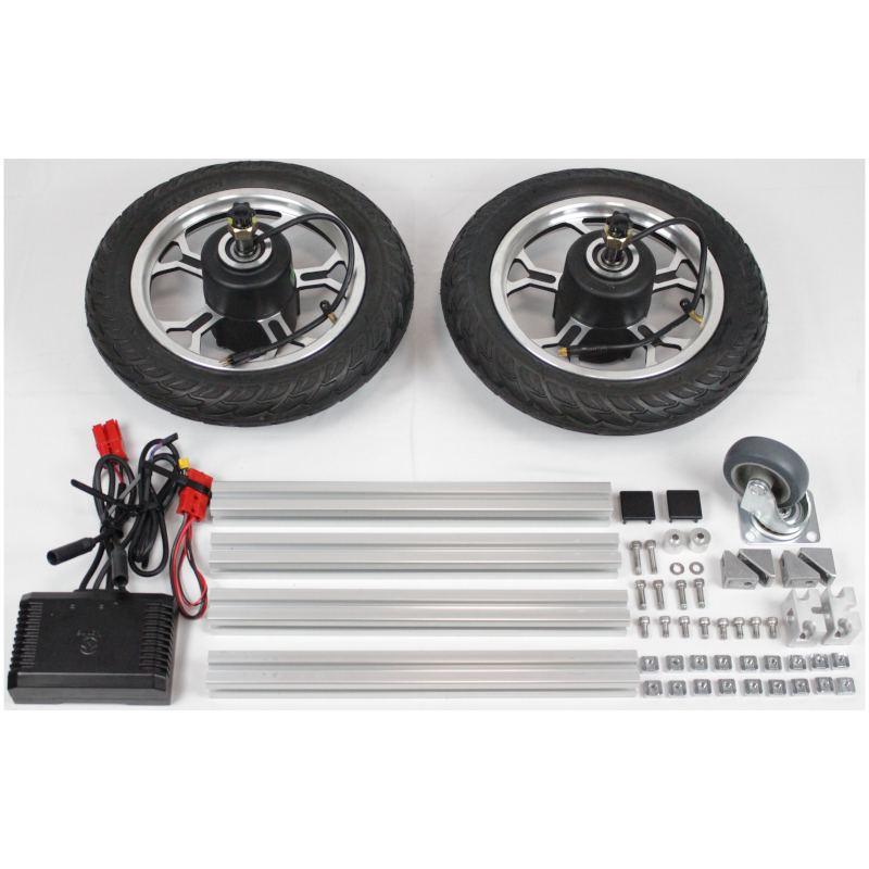
The ATCart combo kit is a DIY parts for ATCart frame set. What will you see from the kit are,
ATCart wheel’s motor 2 pcs
ATCart ESC
30x30x350 mm aluminum frame 4pcs
corner bracket 4pcs
insert nut M6 22pcs
M6x12 bolt 8pcs
M6x20 bolt 4pcs
M6x18 bolt 2pcs
caster wheel 1pc
caster wheel spacer 1pc
wheel’s shaft holder 2pcs
frame end caps 4pcs
How to assemble
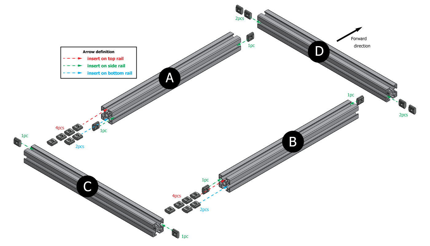
Take all of the frame, and insert all of inserted nut as following image.
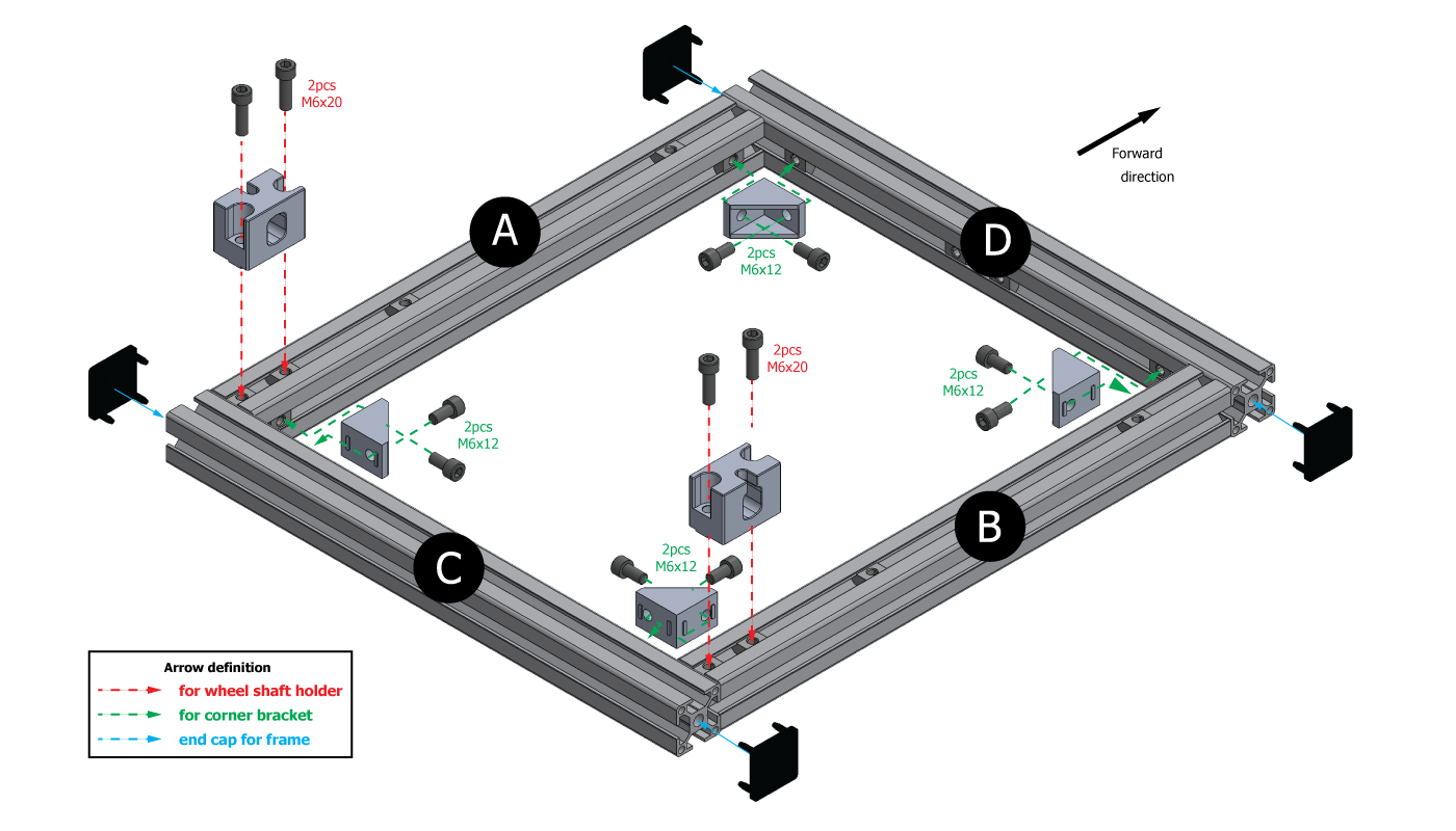
A frame is indicated as left frame, B is as right frame, C is as rear frame, and D is as front frame.
Green arrows are pointing for the inserted nut on the side rail of the aluminum frame.
Red arrows are pointing for the inserted nut on the top rail of the aluminum frame.
Blue arrows are pointing for the inserted nut on the bottom rail of the aluminum frame.
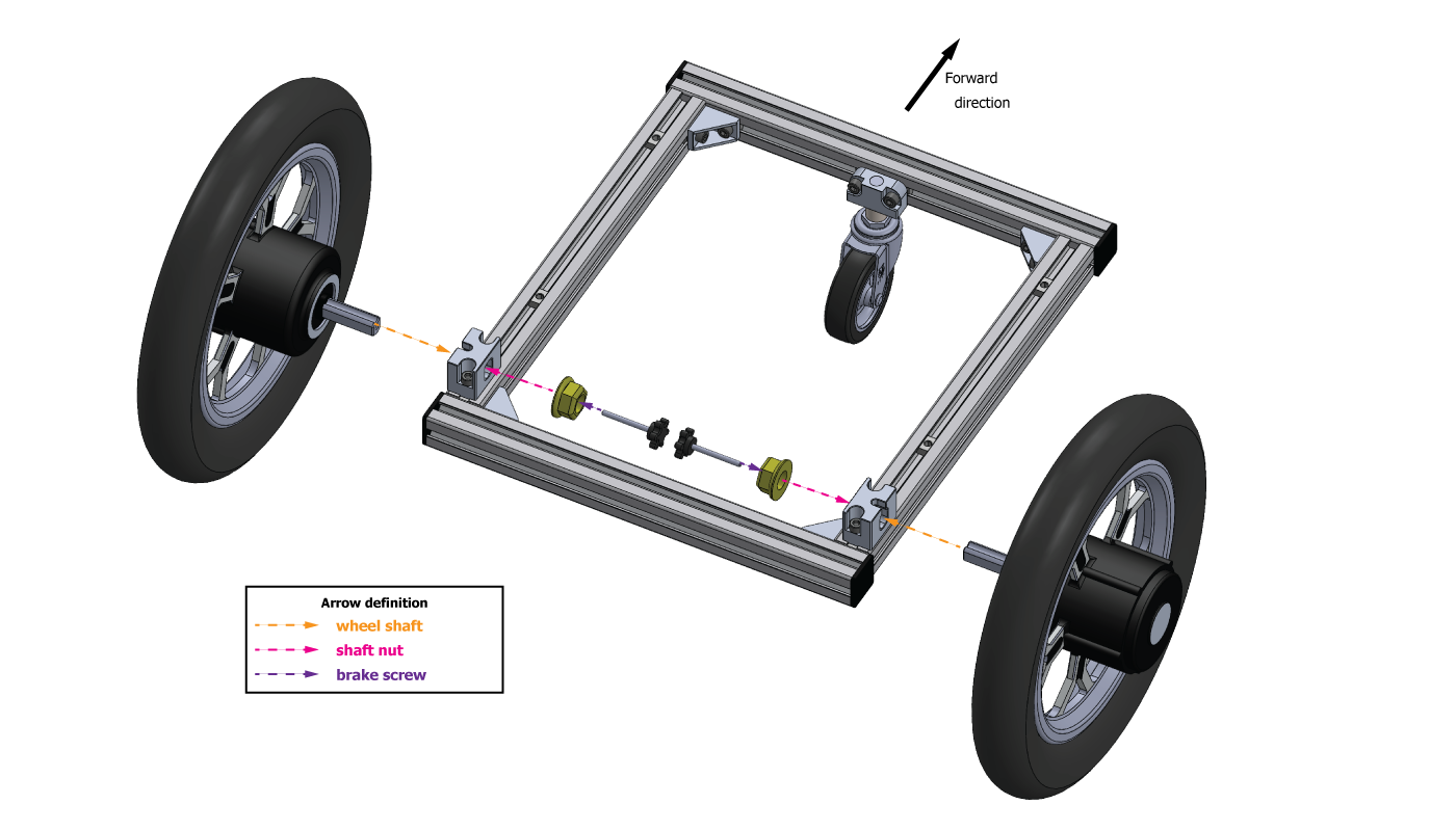
Tight M6x20 on wheel’s shaft holder to inserted nut on top rail of frame A and frame B, then tight M6x12 to frame’s corner bracket in each corner as following image and insert frame end caps.
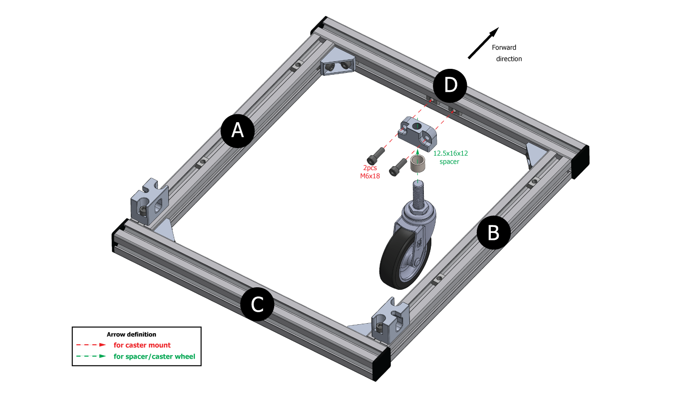
Tight M6x18 through the caster mount to the inserted nut on the frame D, then screw tight the threaded stem caster wheel passing through the spacer from the bottom of the caster mount wheel as shown in the following image.
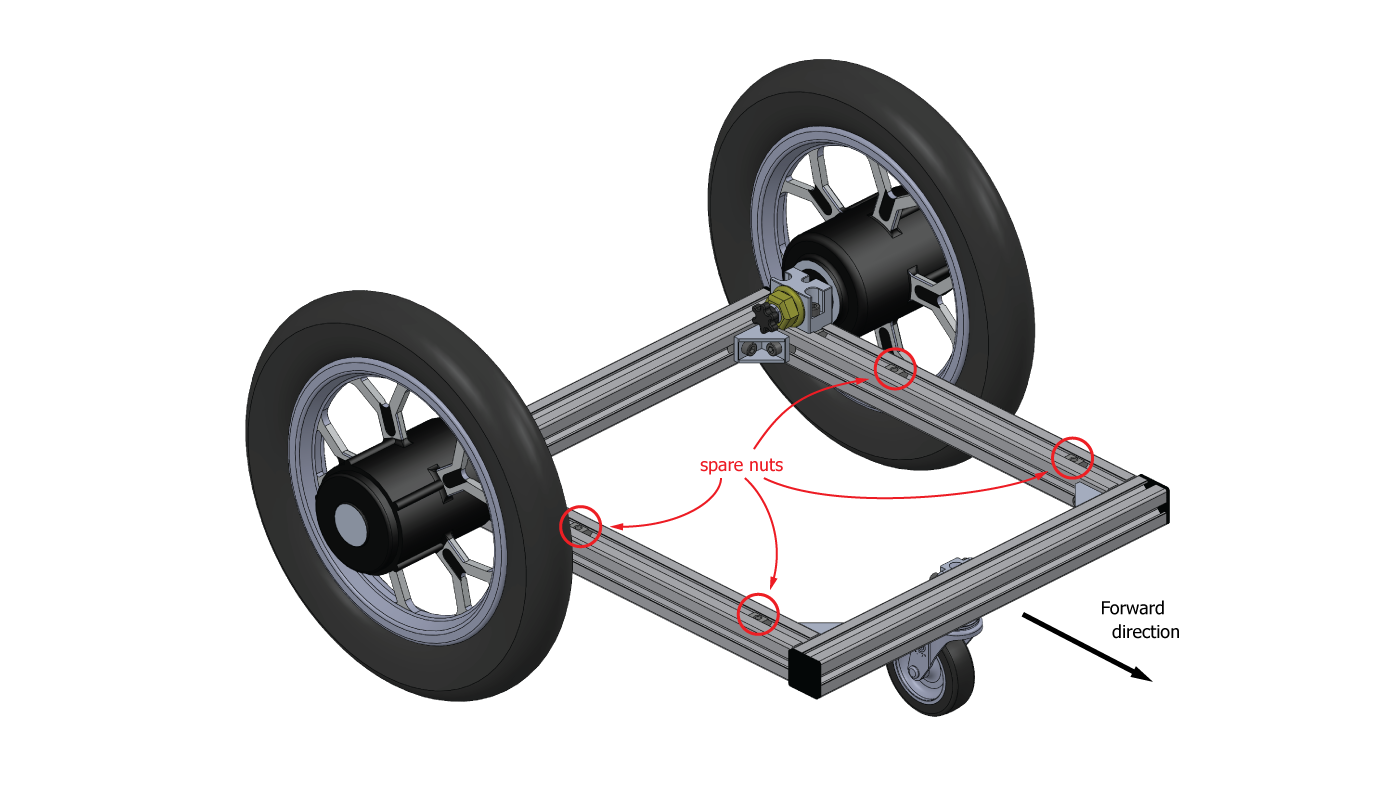
Insert the ATCart wheel motor to each of shaft holder, then lock the wheel’s shaft with holder by hex nut screw, and finally insert the brake screw to wheel’s shaft as following image.
Note
The brake screw is also known as the “parking brake”. It is used to keep the ATCart securely lock or motionless when not in use (or parked). To engange the parking brake, slightly loose the brake screw (thumbscrew) about 3-5 turns or until no tension. To release the parking brake, turn the brake screw back tightly enough (but don’t over-tighten), then the Cart is ready for moving.
There are extra inserted nuts on top and bottom rail, you can use it to lock some board, controller box, or necessary part to the frame.
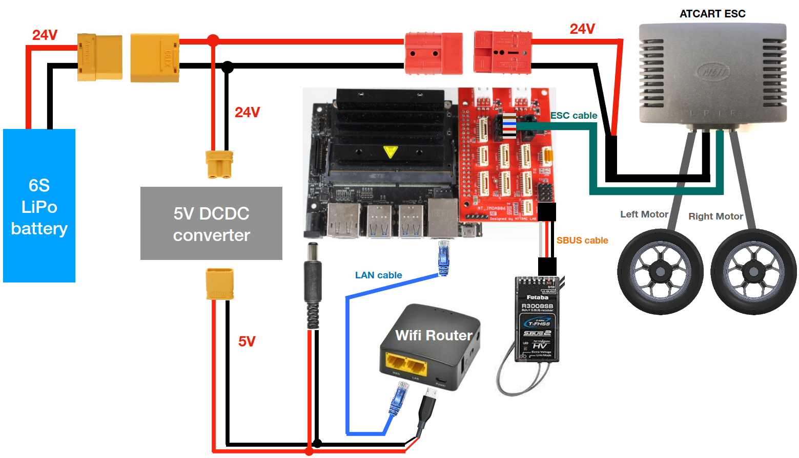
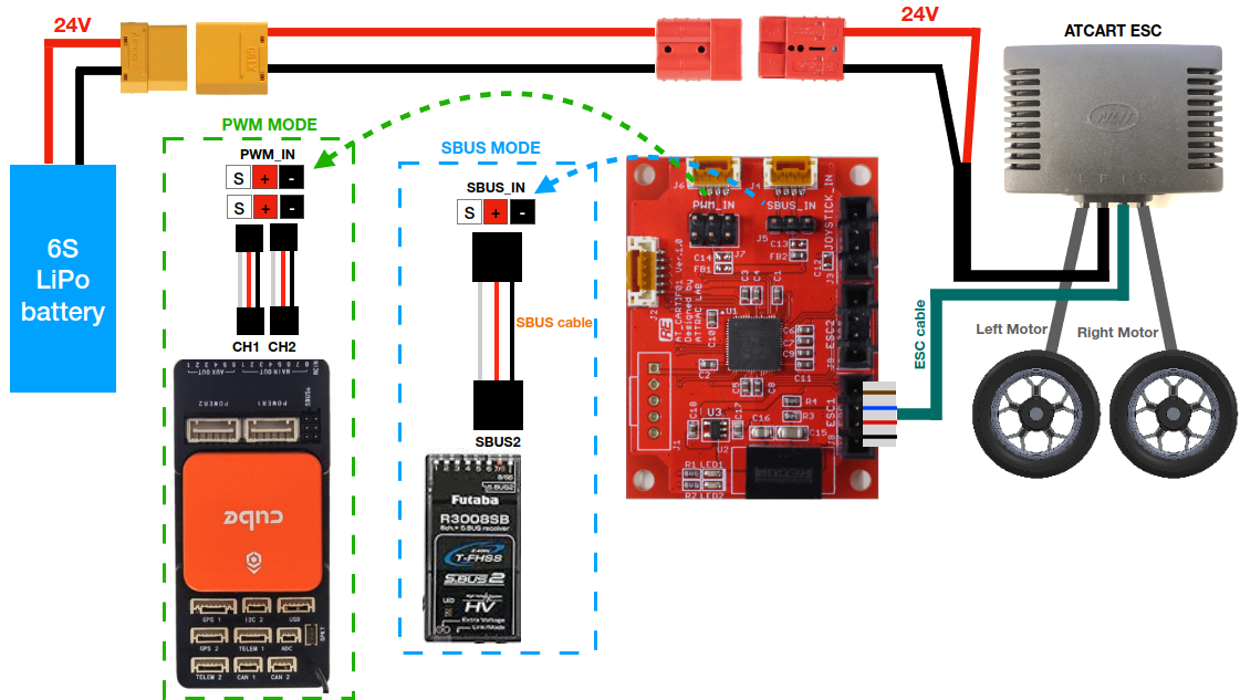
So depends on your application purpose, you could following the connection diagram to use with JMOAB for ROS programming, or connection diagram to use with CARTIF board for RC control or other flight controller.
