JMOAB
The JMOAB is an interface board which allows user to control ATCart motors, relays, move servo, get SBUS data from radio controller, get data from IMU, etc. It is designed to connect to Jetson Nano 40 pins header.
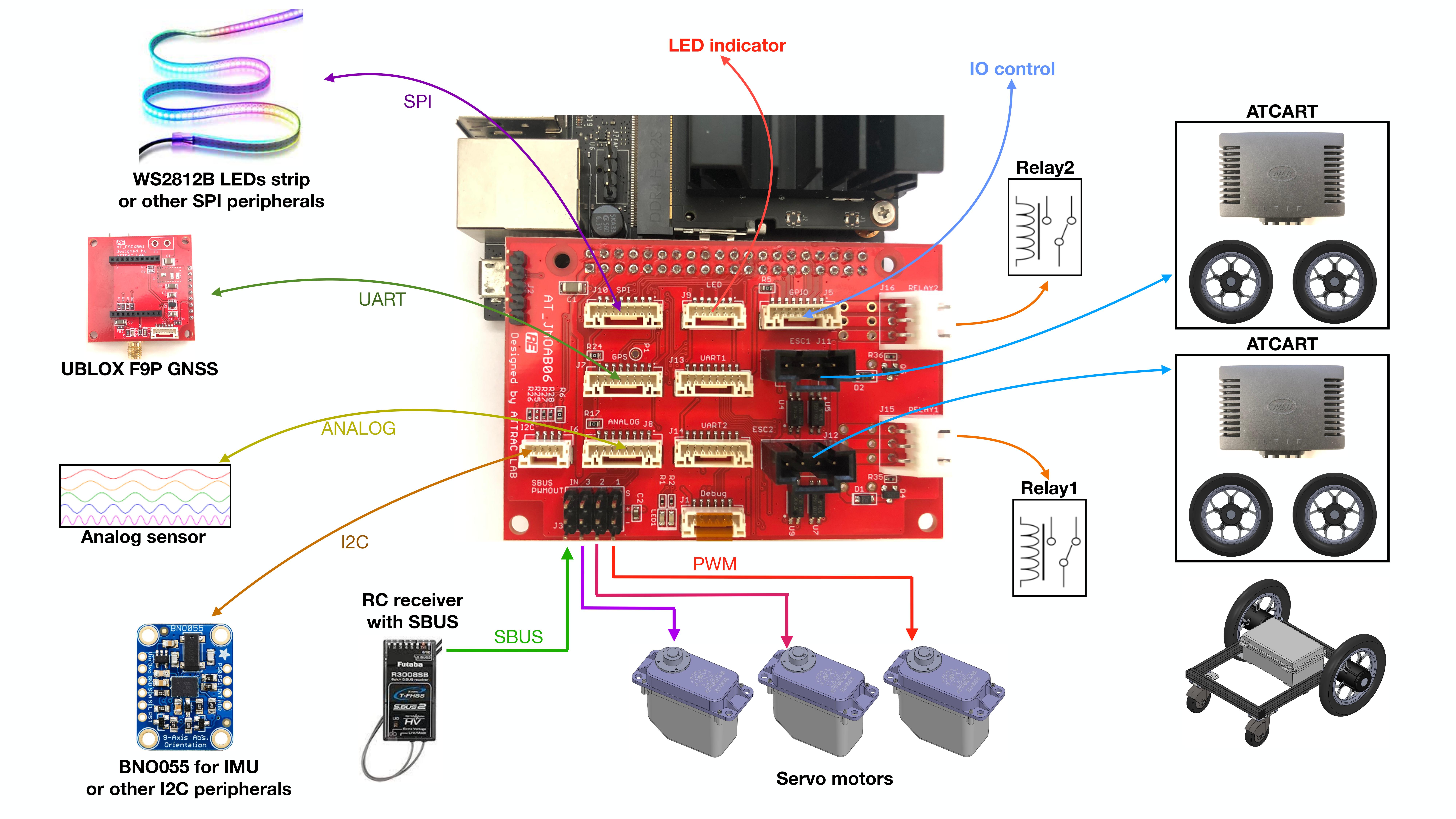
Overview diagram to use JMOAB with ATCart motors
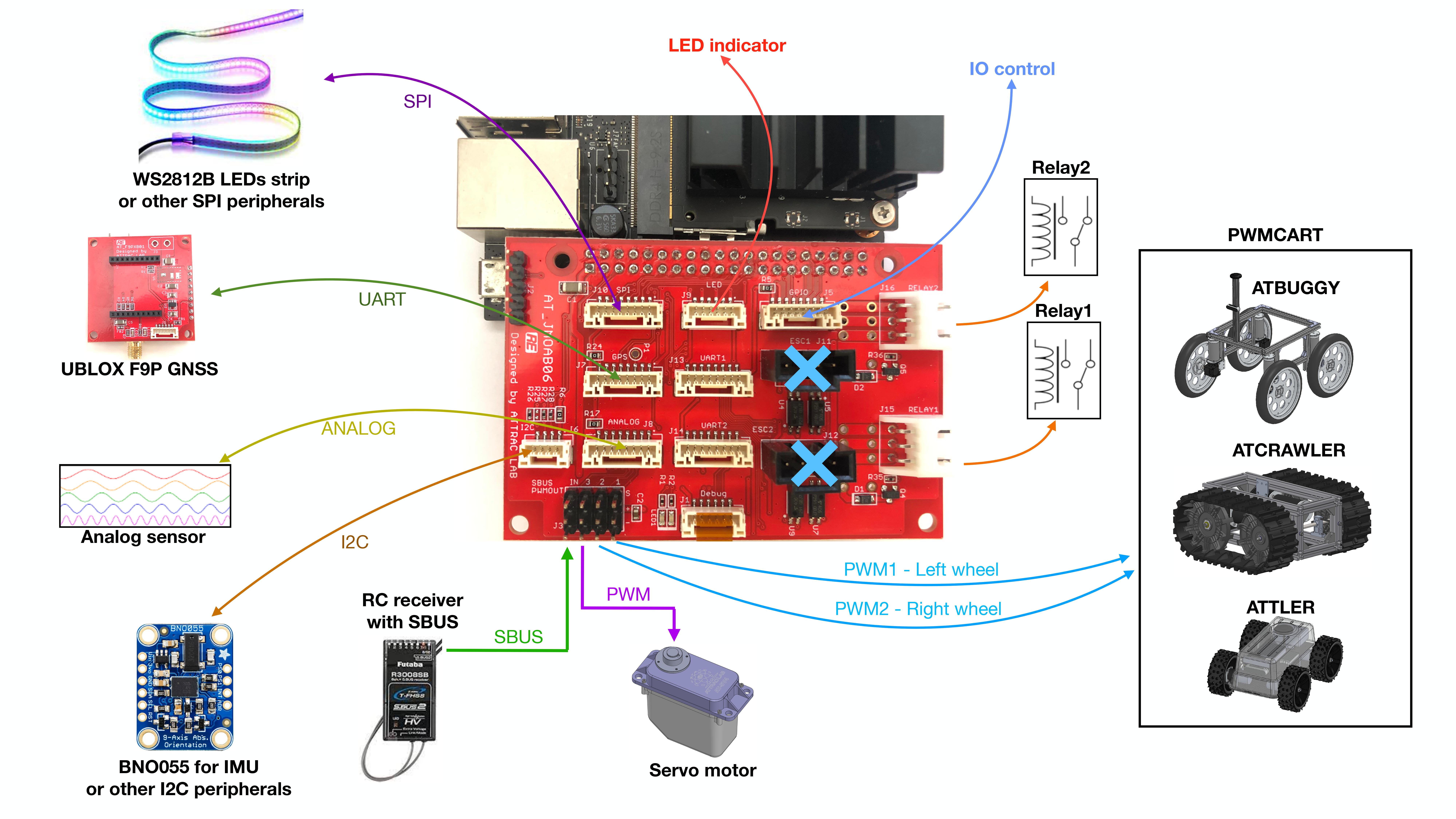
Overview diagram to use JMOAB with PWM cart motors
Flash the firmware
The JMOAB is able to use with ATCart motors and PWM cart motor, in order to use in each case we need to flash the firmware on JMOAB correctly. What you need to prepare to flash the firmware is, 1. Mini Prog3 programmer. 2. Windows OS computer. 3. Download PSoc programmer software to Windows computer.
After we have prepared those 3 things above, next you will need to plug on JMOAB to Jetson Nano, and power on Jetson Nano as usual. Because JMOAB itself could only get power from 40 pins header.
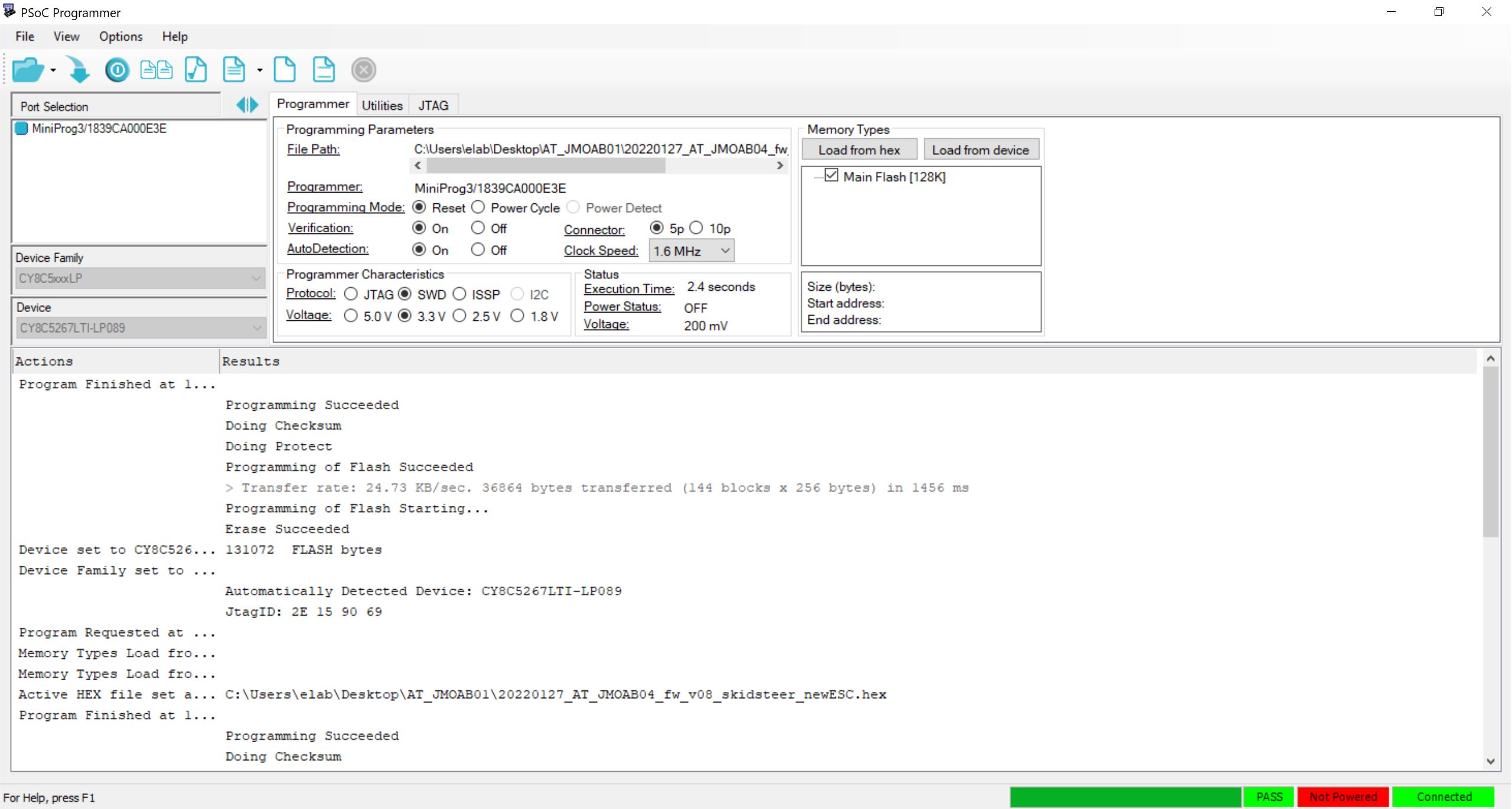
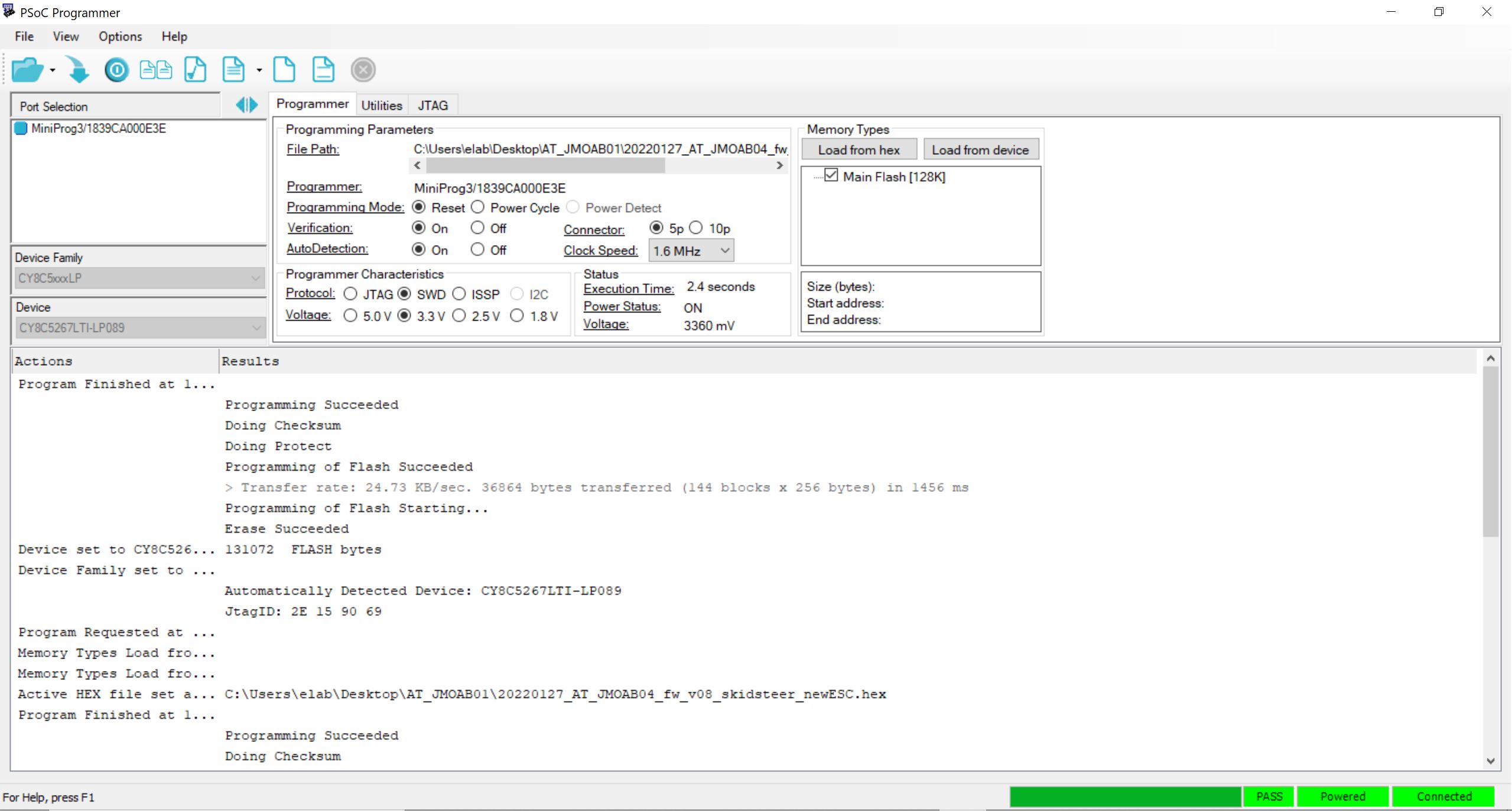
Open up psoc programmer on Windows computer, it will show as following picture,
Please select the option as following.
Programming Mode |
Reset |
Verification |
On |
Connector |
5p |
Clock Speed |
1.6 MHz |
AutoDetection |
On |
Protocol |
SWD |
Voltage |
3.3 V |
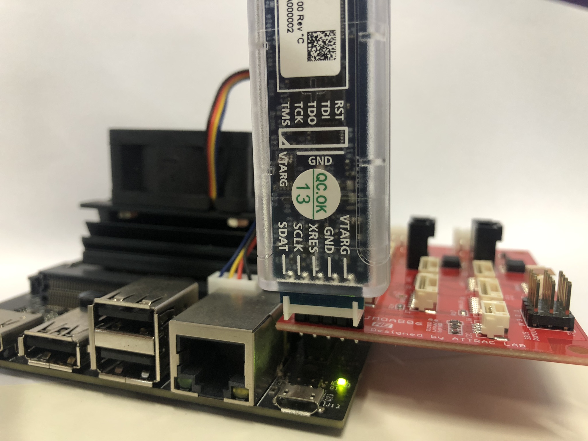
Afer you have confirmed the power on Jetson Nano, and Psoc programmer is opened, then plug the Mini Prog3 Programmer on JMOAB J2 header as the image
Warning
Please becareful to plug it with the correct orientation as in the image, otherwise you could damage your programmer.
You could notice that once the programmer is plugged, the status on application on bottm right corner should be showing green. If not, please try to unplug the USB port and plug again.
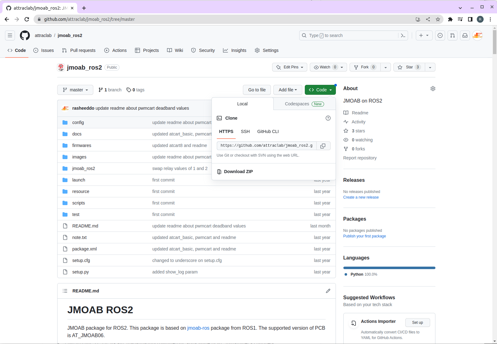
On this Windows computer, we need to download JMOAB firmware from jmoab_ros2 package. Go to the repository, and click on Code green button, and select Download ZIP.
Then back to psoc programmer software, you could select on the Open file menu then select the firwmare you need to use from jmoab_ros2 folder that you just downloaded.
For ATCart motors, please select 20220322_JMOAB06_v1.hex
For PWM Cart motors, please select 20220729_AT_JMOAB06_fw_v09_PWM-ESC.hex
Then click on Program button to flash the firmware to JMOAB. The result should be showing Programming Succeeded.
Once it’s done flashing, you will need to power off and on the Jetson Nano again to take affect of new firmware on JMOAB.
Setup Jetson Nano
Flash the SD card
For the original Jetson Nano deveopment kit (2GB and 4GB), NVIDIA original image is only for Ubuntu18.04, if you’re planning to use with only ROS1 then this is good to go. But if you’re planning to use with ROS2 also, then you are now have two options, 1. Using NVIDIA ROS2 docker with NVIDIA original image 2. Flash SD card with custom Ubuntu20.04 image from QEngineering.
Please flash the SD card according to which ROS version you need.
Install ROS
If you flashed the SD card with original image from NVIDIA, you will need to install ROS1 melodic from here.
If you flashed the SD card with QEngineering image, you could install both ROS1 noetic and ROS2 galactic.
Please follow along the installation process of each ROS version.
Install Package and Dependencies
For original NVIDIA image (Ubuntu18.04)
## For i2c communicate with JMOAB
### we need python2, make sure pip is for python2
sudo pip install smbus2

## If not having workspace yet
cd ~
mkdir -p catkin_ws/src

## Clone jmoab-ros package to workspace
cd ~/catkin_ws/src
git clone https://github.com/rasheeddo/jmoab-ros.git

## Build jmoab-ros package
cd ~/catkin_ws
source /opt/ros/melodic/setup.bash
catkin_make
source ~/catkin_ws/devel/setup.bash

## Setup ROS ENV
## copy those line below to ~/.bashrc file
## it will source the ROS enviroments everytime the new terminal is opened.
## make sure to change <change-to-your-robot-ip> to actual IP, example 192.168.8.100
source /opt/ros/melodic/setup.bash
source ~/catkin_ws/devel/setup.bash
export ROS_MASTER_URI=http://localhost:11311
export ROS_IP=<change-to-your-robot-ip>
export ROS_HOSTNAME=$ROS_IP
For custom image (Ubuntu20.04), there is no need to use jmoab-ros here, we could use jmoab_ros2 instead. But you could install other ROS1 package on catkin_ws with noetic distro.
## For i2c communicate with JMOAB
## we need python3 here, make sure it's pip3
sudo pip3 install smbus2

## other deps
sudo apt install ros-galactic-tf-transformations
sudo apt install python3-colcon-common-extensions
sudo pip3 install transforms3d numpy

## If not having workspace yet
cd ~
mkdir -p ros2_ws/src

## Clone jmoab_ros2 package to workspace
cd ~/ros2_ws/src
git clone https://github.com/attraclab/jmoab_ros2.git

## Build jmoab_ros2 package
cd ~/ros2_ws
source /opt/ros/galactic/setup.bash
colcon build --symlink-install --packages-select jmoab_ros2
source install/local_setup.bash

## Setup ROS2 ENV
## Put this line in ~/.bashrc
export ROS_DOMAIN_ID=1

## If there is only ROS2, you could also put these line in ~/.bashrc
source /opt/ros/galactic/setup.bash
source ~/ros2_ws/install/local_setup.bash

## If there is also ROS1 package you need to use, it's better to source either ROS1 or ROS2 enviroment manually for new terminal.
## Especially, when there is ros1_bridge package
Testing JMOAB with ATCart
Before we start testing here, please make sure you have flashed the ATCart firmware on JMOAB and setup Jetson Nano. If not please go check on upper section.
Confirm the setup
In order to test JMOAB with ATCart, you will need to have the ATCart ESC and motors either from ATCart Combo Kit or ATCart ROS Assemble Set.
Note
We only support the ATCart ESC only from our shop, the back of the black ESC should be showing model number as MN1 WSDC/3+7F&G-X
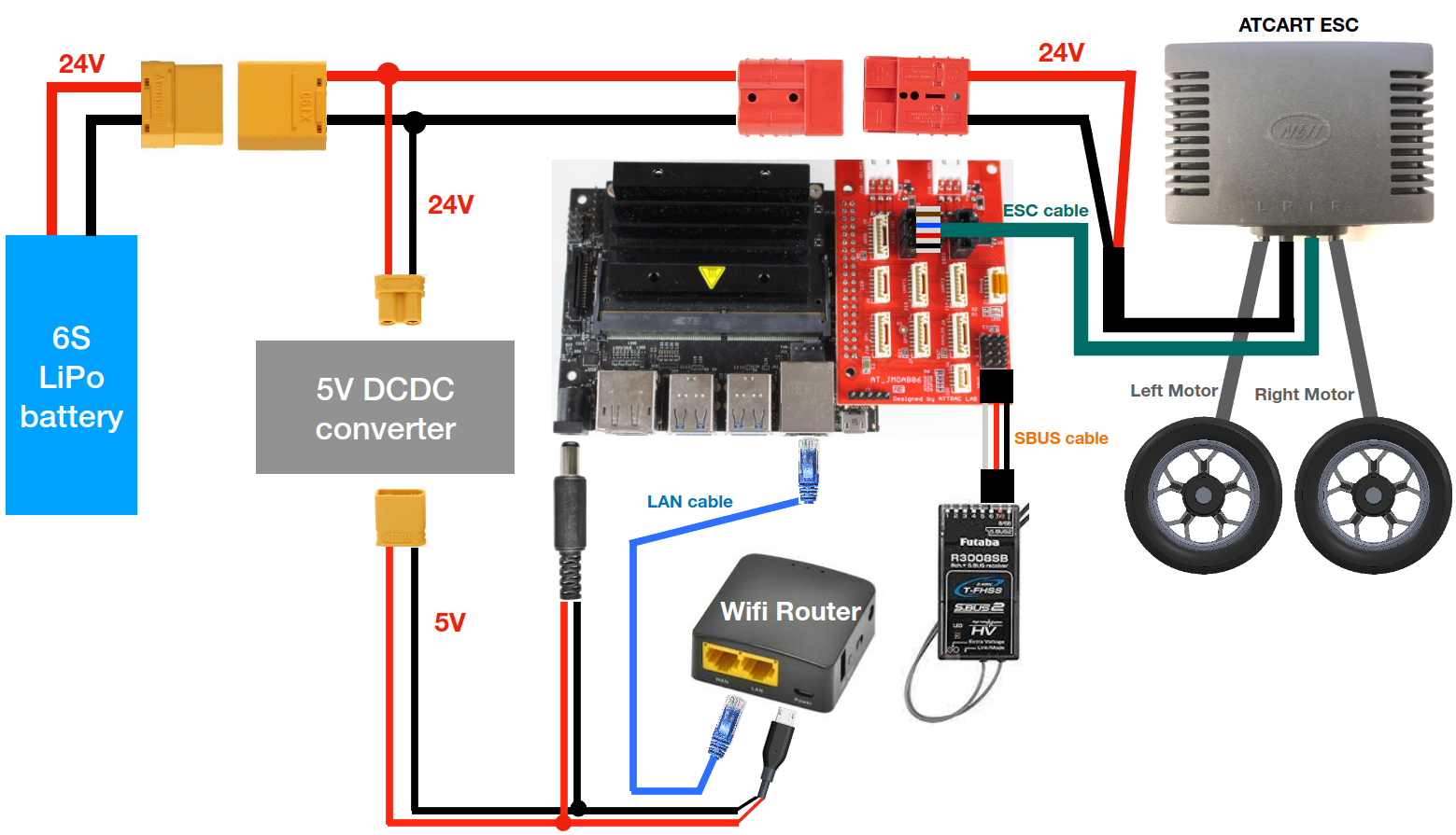
You will need to make sure the connection diagram as below. All of the connector should be plugged on except the battery, we will plug the battery at the end once everything is ready.
Warning
In case you want to unplug orr disconnet the ESC cable from JMOAB.
Don’t unplug the ESC cable from JMOAB when battery is connecting. Please unplug the battery connector from system first, make sure there is no power then you could unplug the ESC cable from JMOAB safely.
JMOAB could be damaged if ESC cable is unplugged during power is supplying.
After everthing is connected, then connect the battery to the system.
Drive testing by manual mode
Then you will need to have Futaba transmitter close to you to operate the cart. Power on the radio transmitter, then you could notice that the LED on radio receiver would turn to green.
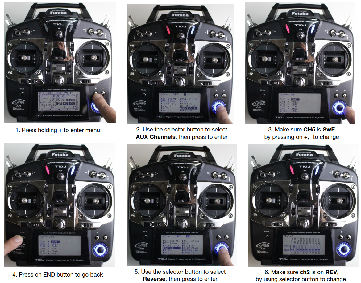
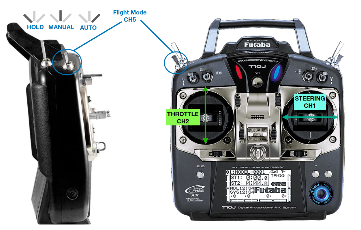
Please make sure your radio transmitter is setup correctly for JMOAB and ATCart, please follow the step below.
After the channel on radio transmitter is setup properly, you could change the flight mode on channel 5 (Switch E) to Manual, then please push the left stick up SLOWLY to make cart moving forward. This is throttle stick or channel2. You could SLOWLY push the right stick left-right to make the cart turning in place (or skidding). This is steering stick or channel1.
If you bring the flight mode to HOLD, then the throttle/steering sticks would be disable, and the cart will stop moving.
Drive testing by ROS topic
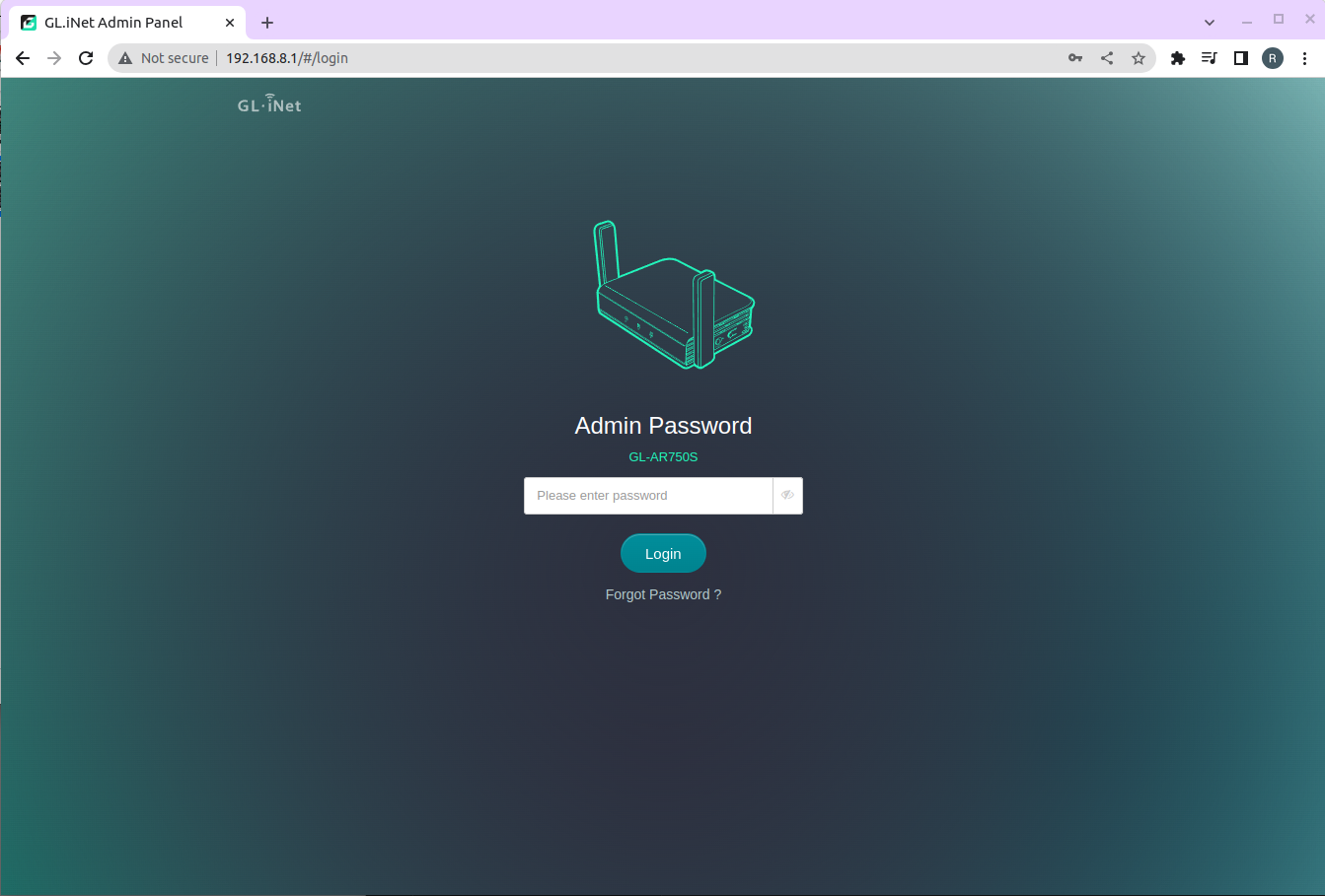
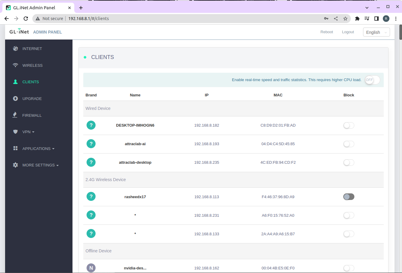
If you are following the setup above, you could access the same network of Jetson Nano by checking on Wifi router SSID and password. If you are using Wifi router from GL-iNet similar to us, you could check the robot IP address by opening the web browser and go to 192.168.8.1 .
You could select on Clients menu to check what is the Jetson Nano IP address, then SSH to the robot with username and password.
jmoab-ros and jmoab_ros2 packages are made by Python, for more detail please check in the Github repo of each one. Let’s try to drive the ATCart by ros topic.
For original NVIDIA image (Ubuntu18.04)
## Terminal1
roscore

## Terminal2
## start atcart_basic node
## you could see what topic is published or is subcribing from terminal info
rosrun jmoab-ros atcart_basic.py

## Terminal3
## publish cmd_vel topic to atcart_basic
rostopic pub -r 10 /cmd_vel geometry_msgs/Twist "{'linear': {'x': 0.2}, 'angular': {'z': 0.0}}"
Now if we change the flight mode on radio transmitter to AUTO, you could notice that the ATCart’s wheels start spinning. If you try change the value of linear.x or angular.z to see more difference.
Note
If you stop sending /cmd_vel the cart will automatically stop, this is a safety function in atcart_basic node in case the autonomous drive node got crashed during operation.
For custom image (Ubuntu20.04)
## Terminal1
## start atcart_basic node
## you could see what topic is published or is subcribing from terminal info
ros2 run jmoab_ros2 atcart_basic

## Terminal2
## publish cmd_vel topic to atcart_basic
rostopic pub -r 10 /cmd_vel geometry_msgs/Twist "{'linear': {'x': 0.2}, 'angular': {'z': 0.0}}"
Now if we change the flight mode on radio transmitter to AUTO, you could notice that the ATCart’s wheels start spinning. If you try change the value of linear.x or angular.z to see more difference.
Note
If you stop sending /cmd_vel the cart will automatically stop, this is a safety function in atcart_basic node in case the autonomous drive node got crashed during operation.
You could try to get SBUS values from each channel by subscribing on /jmoab/sbus_rc_ch topic.
Connect BNO055 and Get IMU data
jmoab-ros and jmoab_ros2 are supported only BNO055 IMU, if you have other IMU you will need to make your own driver node.
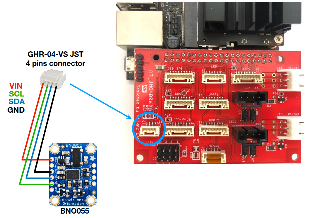
We are using BNO055 breakout board from Adafruit, please make a wiring as the image below. The JST 4 pins connector is GHR-04-VS.
Then just plug it on I2C port of JMOAB.
Calibrate sensors
You will need to do sensor calibration first to get offset values. Please follow along the step below. If the IMU is placed on the cart, please take it off first to let it free to move.
cd ~/catkin_ws/src/jmoab-ros/example
python bno055_compass_calibrate.py

## you would see it's printing out status of each sensor
## calib_stat 0 | sys_stat 0 | gyr_stat 0 | acc_stat 0 | mag_stat 0
we need to make gyr_stat, acc_stat, mag_stat equal to 3, then sys_stat and calib_stat will be changed by itself.
Calibrate gyroscope: you just need to place BNO055 board steady on table, then it
gyr_statwill easily change to 3Calibrate accelerometer: you will need to place the board in various orientation for 2-3 seconds, for example in 45, 90 180, -45, -90 degrees. The
acc_statwill try to change to 3 if success.Calibrate magnetometer: Take the board and draw some circle or “8” character shape in the air, then
mag_statwill change to 3.
If all is success you will see the list of offset value printing, and the program is terminated. If all of offset is showing 0, please try to start the script one more time then it will immediately show the correct offset value.
The calibration_offset.txt stores all the offset value in the same directory.
cd ~/ros2_ws/src/jmoab_ros2/scripts
python3 bno055_calibrate.py

## you would see it's printing out status of each sensor
## calib_stat 0 | sys_stat 0 | gyr_stat 0 | acc_stat 0 | mag_stat 0
we need to make gyr_stat, acc_stat, mag_stat equal to 3, then sys_stat and calib_stat will be changed by itself.
Calibrate gyroscope: you just need to place BNO055 board steady on table, then it
gyr_statwill easily change to 3Calibrate accelerometer: you will need to place the board in various orientation for 2-3 seconds, for example in 45, 90 180, -45, -90 degrees. The
acc_statwill try to change to 3 if success.Calibrate magnetometer: Take the board and draw some circle or “8” character shape in the air, then
mag_statwill change to 3.
If all is success you will see the list of offset value printing, and the program is terminated. If all of offset is showing 0, please try to start the script one more time then it will immediately show the correct offset value.
The calibration_offset.txt stores all the offset value in the same directory.
Run the IMU node
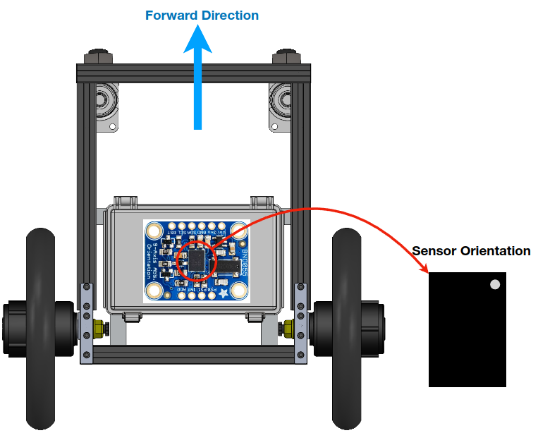
After we have done the calibration from now we could run the another node to get IMU data. If you are going to place IMU back on the cart, please make sure to have the sensor orientation as the image.
## Terminal1
roscore

## Terminal2
## start the node
rosrun jmoab-ros bno055_ahrs.py
Now you could list the topic, and will see,
/imu/dataas raw sensor_msgs/Imu message/jmoab/ahrsas std_msgs/Float32MultiArray [roll, pitch, yaw] in degrees
You could also notice this node is subscribing on /ublox/fix, /jmoab/sbus_rc_ch, and /jmoab/cart_mode, because when we are using this outdoor with GPS, this node could estimate the correct heading angle by using GPS data when the robot is moving in straight line.
## Terminal1
ros2 run jmoab_ros2 bno055
Now you could list the topic, and will see,
/imu/dataas raw sensor_msgs/Imu message/jmoab/ahrsas std_msgs/Float32MultiArray [roll, pitch, yaw] in degrees
You could also notice this node is subscribing on /fix, /jmoab/sbus_rc_ch, and /jmoab/cart_mode, because when we are using this outdoor with GPS, this node could estimate the correct heading angle by using GPS data when the robot is moving in straight line.
If you could see data correctly on jmoab/ahrs topic when moving the robot, then it’s ready to go. In case when you need to use raw data of IMU for example with SLAM or EKF, the imu/data is the one you need.
