ATCrawler Basic with ROS
The ATCrawler basic assemble set allow you to use any computer with ROS for a robot development.
Once you have the ATCrawler basic with you, it would come with our custom ESC for high power driven motors the AT_MOTOR-DRIVER_100A_2ch_ver.9.0 with aluminum heatsink attached on the box’s lid.
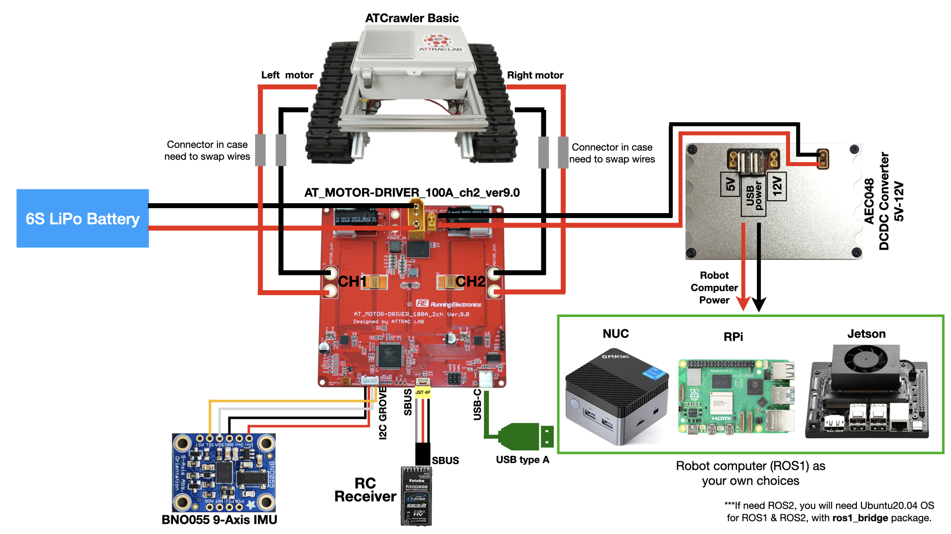
To use ATCrawler basic as ROS mobile robot platform, please follow the connection diagram below.
It depends on which computer you would like to use, you may need to prepare DC-DC regulator to provide sufficient and regulated voltage to the computer.
Warning
For best practice when developing the robot, it is highly recommended to use one single power source to provide power to all component on the robot. This will eliminate the ground-loop problem which cause strange unpredictable behavior in electronics.
If it is hard for you to find or make a stable DC-DC regulator, I recommend to buy it from us. Our AEC048 DC-DC regulator could output stable 5V and 12V and also two USB ports (5V). It could take input voltage from 20V to 60V.
If you don’t have BNO055 IMU, that is totally fine. The ESC could still working but you will just not see IMU ROS topic publishing.
I highly recommend to have RC receiver with SBUS connect on ESC, because you could immediately test the driving function in MANUAL control mode.
Manual Control by RC
There is a chance when your ROS program crashed or your computer is shutdown during the robot is moving. In order to take control from computer to yourself, we are using RC receiver as a master to select whether to use ROS control or Radio control. I recommend to use Futaba T10J (or any model with SBUS output) as radio control device.
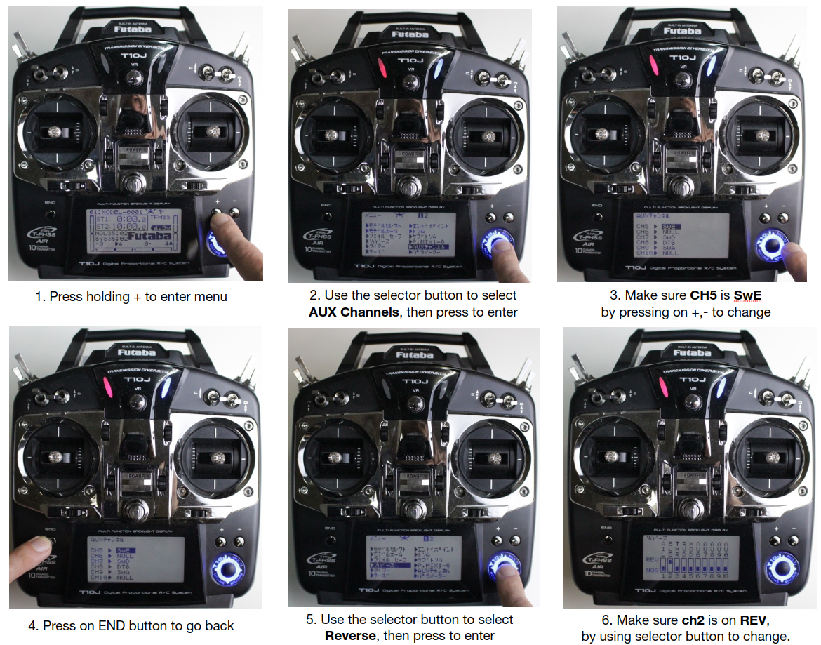
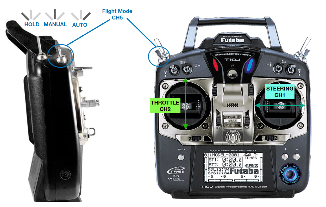
If this is your first time using radio controller, please make sure that you have assigned the correct channel on radio’s sticks and switches as following image.
You will need to make sure that,
left stick up-down direction is set to CH2, we call this as Throttle to move the cart forward or backward.
Note
As default from Futaba transmitter, CH2 should be assigned to reverse. On some model, the CH2 is set to reverse as default, but if you found that the cart is moving oppositely from you stick, then please check on stick reverse setup.
right stick left-right direction is set to CH1, we call this as Steering to turn the cart to left or right direction.
switch E is assigned as CH5 for mode changing switch. As shown in the picture, the cart will be on HOLD mode if you push this switch to the back position, and will be on MANUAL if you push it on middle, and will be on AUTO (ROS control) if switch is on front position.
Once all the necessary channels are setup correctly, then plug battery on the ESC. Once the cart got power, you will need to switch from HOLD to MANUAL (even it’s already in MANUAL, you will have to do again).
Warning
The speed of the ATCrawler is proportional to the RC transmitter stick position, the middle position (neutral position) of stick means NO SPEED.
End position of stick (Full throttle or Full steering) means FULL SPEED.
Then try to move the cart SLOWLY by pushing on the throttle and steering sticks. If you are able to control the cart manually, then everything is working fine.
If you cannot control the cart for some reason, please try following solution,
Make sure the RC receiver is binded with RC transmitter, the LED on receiver should be green when transmitter is ON.
Try switching from HOLD to MANUAL couple times slowly.
Try restart the whole system one more time.
Computer Control by ROS
Once you confirmed you can take control the cart by Radio controller, then let’s try to connect to robot computer and send ROS topic command.
By default, the ESC is communicating with computer via ROS1 topics. If you are planning to use ROS2, you will need to use Ubuntu20.04 with ROS1 noetic and ROS2 galactic installed, then using ros1_bridge package to bridge ROS1 topic from ESC to ROS2 environment.
Install the utility package
There are utility packages which can help you to work with this ESC easily.
Please install ROS1 (and ROS2) according to what you need and all dependencies as written on the Github repositories above.
Note
Please make sure you have setup the udev rules for ESC, it should be shown as /dev/md100a.
This will avoid USB conflict when there are more USB devices plugging in the same time.
Setup ROS environment
Once everything is installed, try to setup the ROS environment.
You can put these lines on your ~/.bashrc file
## you must change <your-ip-address> to exact of your computer IP address
export ROS_MASTER_URI=http://localhost:11311
export ROS_IP=<your-ip-address>
export ROS_HOSTNAME=$ROS_IP
## For ROS1
## you must change <your-ip-address> to exact of your computer IP address
export ROS_MASTER_URI=http://localhost:11311
export ROS_IP=<your-ip-address>
export ROS_HOSTNAME=$ROS_IP

## For ROS2
export ROS_DOMAIN_ID=1
Run ROS node
After that we may need to open couple terminals and run following nodes,
Each terminal will need to source ROS environment correctly
## Terminal 1
source /opt/ros/noetic/setup.bash
roscore

## Terminal 2
source /opt/ros/noetic/setup.bash
rosrun rosserial_python serial_node.py  _port:=/dev/md100a _baud:=921600

## Terminal 3
## ~/catkin_ws/src is where md100a_ros1_utils is installed
source /opt/ros/noetic/setup.bash
source ~/catkin_ws/devel/setup.bash
rosrun md100a_ros1_utils cmd_vel_converter
## Terminal 1
## For ROS1
source /opt/ros/noetic/setup.bash
roscore

## Terminal 2
## For ROS1
source /opt/ros/noetic/setup.bash
rosrun rosserial_python serial_node.py  _port:=/dev/md100a _baud:=921600

## Terminal 3
## For ros1_bridge
## ~/dev_ws/src is where ros1_bridge is installed.
source /opt/ros/noetic/setup.bash
source /opt/ros/galactic/setup.bash
source ~/dev_ws/install/local_setup.bash
ros2 run ros1_bridge dynamic_bridge

## Terminal 4
## For ROS2
## ~/dev_ws/src is where md100a_ros2_utils is installed.
source /opt/ros/galactic/setup.bash
source ~/dev_ws/install/local_setup.bash
ros2 run md100a_ros2_utils cmd_vel_converter
The cmd_vel_converter is doing simple task, is to convert well-known cmd_vel topic from any Navigation package to /md100a/pwm_cmd topic to drive the ATCrawler.
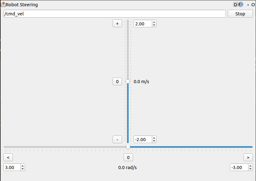
For example, you can use rqt_robot_steering package, a simple GUI to send cmd_vel topic to any subscription node.
## Terminal 4
source /opt/ros/noetic/setup.bash
rosrun rqt_robot_steering rqt_robot_steering
## Terminal 5
source /opt/ros/galactic/setup.bash
ros2 run rqt_robot_steering rqt_robot_steering
You could send throttle or steering speed by move the slider on GUI.
Warning
Similar to RC transmitter, the more slider goes, the more speed it is. Please try putting something to lift up the ATCrawler, not to let rubber tracks touch on ground. So you can test controlling safely.
Once you get use to it, then try running it on the ground.


