ATCrawler BLDC with ROS2
The ATCrawler BLDC assemble set allow you to use any computer with ROS2 for a robot development.
To use ATCrawler BLDC as ROS2 mobile robot platform, please follow the connection diagram below.
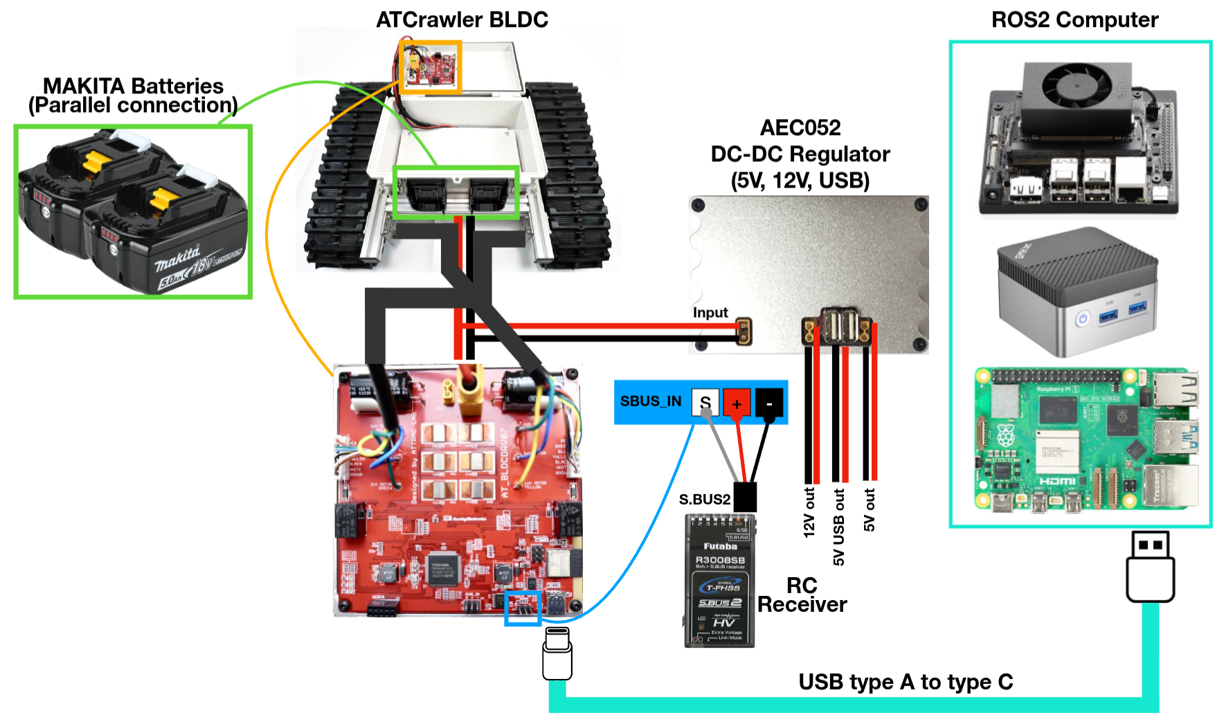
It depends on which computer you would like to use, you may need to prepare DC-DC regulator to provide sufficient and regulated voltage to the computer.
For example in the connection diagram above, there is AEC052 DC-DC regulator which can provide 5V output from XT30 port and from 2x USB ports to power Raspberry Pi, in case some computer like Jetson Orin Nano or NUC box, there is 12V output from XT30 port.
Warning
For best practice when developing the robot, it is highly recommended to use one single power source to provide power to all component on the robot. This will eliminate the ground-loop problem which cause strange unpredictable behavior in electronics.
It’s highly recommended to have RC receiver and connect via SBUS port because you can control the robot manually by RC transmitter. You need to have computer on the system and AT_BLDCDRV07 USB-C is connected to computer to provide 5V to SBUS port.
Manual Control by RC transmitter
There is a chance when your ROS program crashed or your computer is shutdown during the robot is moving. In order to take control from computer to yourself, we are using RC receiver as a master to select whether to use ROS control or Radio control. I recommend to use Futaba T10J (or any model with SBUS output) as radio control device.
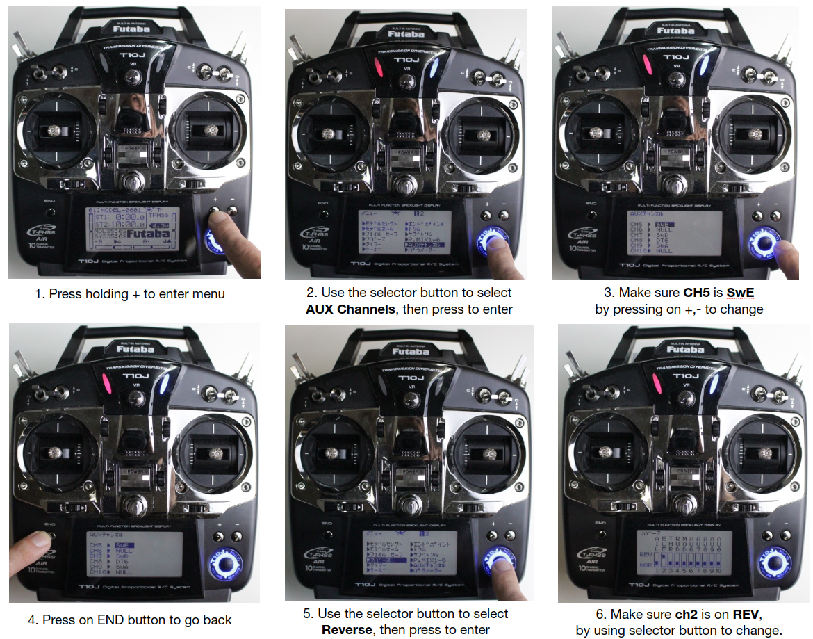
If this is your first time using radio controller, please make sure that you have assigned the correct channel on radio’s sticks and switches as following image.
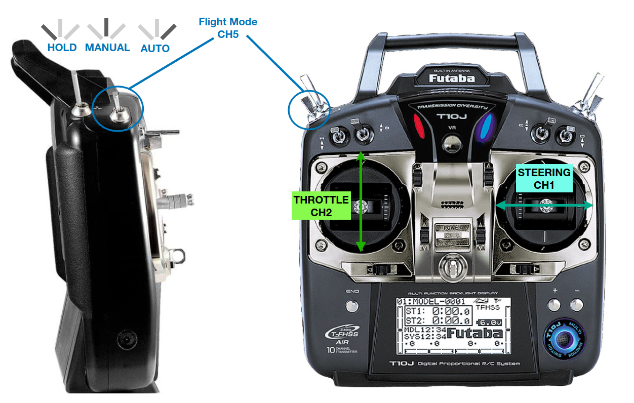
You will need to make sure that,
left stick up-down direction is set to CH2, we call this as Throttle to move the robot forward or backward.
Note
As default from Futaba transmitter, CH2 should be assigned to reverse. On some model, the CH2 is set to reverse as default, but if you found that the cart is moving oppositely from you stick, then please check on stick reverse setup.
right stick left-right direction is set to CH1, we call this as Steering to turn the robot to left or right direction.
switch E is assigned as CH5 for mode changing switch. As shown in the picture, the robot will be on HOLD mode if you push this switch to the back position, and will be on MANUAL if you push it on middle, and will be on AUTO (ROS control) if switch is on front position.
Once all the necessary channels are setup correctly, then plug Makita battery on the battery holder, you can plug only one but two batteries could make the robot stays longer (parallel connection). Once the robot got power, you will need to switch from HOLD to MANUAL (even it’s already in MANUAL, you will have to do again).
Warning
The speed of the ATCrawler BLDC is proportional to the RC transmitter stick position, the middle position (neutral position) of stick means NO SPEED.
End position of stick (Full throttle or Full steering) means FULL SPEED.
Then try to move the cart SLOWLY by pushing on the throttle and steering sticks. If you are able to control the cart manually, then everything is working fine.
If you cannot control the cart for some reason, please try following solution,
Make sure the RC receiver is binded with RC transmitter, the LED on receiver should be green when transmitter is ON.
Try switching from HOLD to MANUAL couple times slowly.
Try restart the whole system one more time.
Software Preparation
There is ESP32 microcontroller board built-in the AT_BLDCDRV07, it’s using micro-ros to publish and subscribe ROS2 topics. On your robot computer, please install micro ROS agent, please create separate workspace , and build micro-ros-agent. This package will allow us to get/set data from micro-ros from ESP32.
There is a utility ROS2 package which can help you work with AT_BLDCDRV07 board easily, it’s called bldc_utils package, so please clone it to your ROS2 project workspace on robot computer.
Run ROS2 nodes
After setup both hardware and software, then we can try to start ROS2 nodes as following,
## Terminal 1
## source micro-ros-agent ws environtment
## assume it is ~/uros_ws
source ~/uros_ws/install/local_setup.bash

## start micro-ros-agent
ros2 run micro_ros_agent micro_ros_agent serial --dev /dev/ttyACM0
## you will need to select the correct /dev/tty* device
AT_BLDCDRV07 ROS2 topics
All of the ROS2 topic from AT_BLDCDRV07 is just std_msgs, so there is no custom message.
QoS of all topics are BEST_EFFORT, KEEP_LAST, and depth = 1. To subscribe or publish the topics, please make sure to have correct QoS.
/BLDCRV/driver_mode_fb : this will show the robot state according to the RC transmitter CH5, 0 is HOLD (no movement), 1 is MANUAL (RC control), 2 is AUTO (or ROS control). If radio transmitter is power off, the mode will be 2 automatically. The topic is publishing from AT_BLDCDRV07 board, robot computer can subscribe to check the robot state.
Message Type
std_msgs/msg/UInt8
Msg Interval
continuous
/BLDCRV/driver_mode : the AT_BLDCDRV07 is subscribing to this topic then robot computer can publish to change the mode, and it will reflect to BLDCRV/driver_mode_fb.
Message Type
std_msgs/msg/UInt8
Msg Interval
once
/BLDCRV/speed_fb : this will show the estimate rpm of the motors, AT_BLDCDRV07 is publishing this. Note that the value might not be exact as actual rpm according to the payload.
Message Type
std_msgs/msg/Float32MultiArray
Value
[left motor rpm, right motor rpm]
Msg Interval
continuous
/BLDCRV/speed_cmd : this topic will set the speed to the motors, AT_BLDCDRV07 is subscribing to this topic, then robot computer has to publish.
Message Type
std_msgs/msg/Int16MultiArray
Value
[left motor rpm, right motor rpm]
Msg Interval
continuous
/BLDCRV/batt_v : this will show the voltage value of battery. AT_BLDCDRV07 is publishing this topic.
Message Type
std_msgs/msg/Float32
Value
Voltage of battery
Msg Interval
continuous
/BLDCRV/sbus_rc_ch : you can get data of all SBUS channel and use it for something else like trigger switch or use signal to do some tasks. AT_BLDCDRV07 is publishing on this.
Message Type
std_msgs/msg/UInt16MultiArray
Msg Interval
continuous
/BLDCRV/error : the error code of motor driver. AT_BLDCDRV07 is publishing on this.
Message Type
std_msgs/msg/UInt8
Msg Interval
continuous
With micro-ros-agent running, you could see this topics showing.
Utility package node
In order to run this robot with the conventional /cmd_vel topic, you will need to run utility node as following,
## Terminal 1
## source ros2 workspace environment
ros2 launch bldcdrv_utils bldcdrv.launch.py
This will start the cmd_vel_converter node with the default parameters setup as
rpm_min = 0.0 rpm_max = 137.0 vx_max = 2.0 wz_max = 2.0 wheel_base = 0.75 show_log = True
Normally, the we only need to change wheel_base in order to let the cmd_vel_converter calculate /BLDCRV/speed_cmd correctly from /cmd_vel, so you can restart the launch file as following,
## Terminal 1
## source ros2 workspace environment
## Make sure to set correct wheel_base value
ros2 launch bldcdrv_utils bldcdrv.launch.py wheel_base:=0.49
Make sure to switch CH5 to ROS control mode or publish /BLDCRV/driver_mode as 2, then you can use a tool like rqt_robot_steering to drive the robot.